Connectors Manipulation
Add Connector
The visualizer offers five different ways for connecting Graphic Symbols.
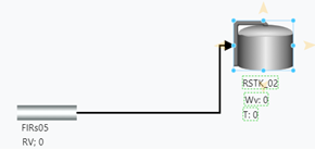
Using Display Toolbar (Connect on tap)
- Select the source Graphic Symbol on the display.
- Select the Connect on Tap icon.
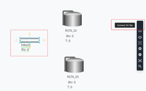
- Select the destination Graphic Symbol on the display.
Using Style Tab of the Selected Graphic Symbol (Connect on tap)
- Select the source Graphic Symbol on the display.
- In the Style Tab (bottom) Select the Connect on Tap icon.
- Select the destination Graphic Symbol on the display.
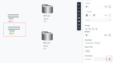
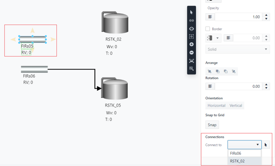
Using the Style Tab of the selected Graphic Symbol (By Name)
- Select the source Graphic Symbol on the display.
- In the Style Tab (bottom) and choose the destination from the drop down. The connection is automatically added.
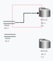
Select and Drag the Connector
- Select the source Graphic Symbol and click on the yellow arrow.
- A connector is added, select the connector.
- Drag the connector to the Destination Graphic Symbol.
Using the SFConnector or SFConnection prefab
- Open the Graphic Template Library.
- Open the Sigmafine Connector Prefab section.
- Select the connector and drag it into the display canvas.
- Drag the origin of the connector on the source Graphic Symbol.

- Drag the end of the connector onto the destination Graphic Symbol.
When a connector is created between two Graphic Symbols both referencing a Sigmafine Element, then a connection is created in the Model as well. The creation of a Model connection is subjected to the Sigmafine Modeling constraints.
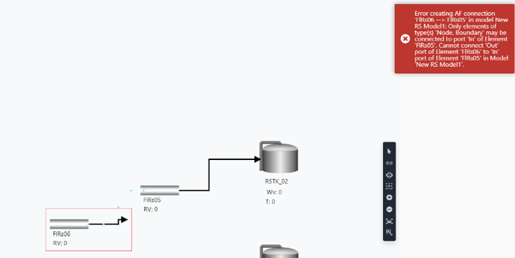
Invalid Connector
An attempt to create a connector in a display may raise an error when the Model connection is not consistent with the Sigmafine constraints.
As an example, trying to connect two flows:
An error is raised, and the connector is updated.
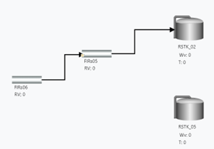
Change Connector Path
Connectors are drawn on the display according to an optimized path that avoids overlapping other symbols and lines on the display. The start of a connector attaches the source Graphic Symbol on the center right and the end of the connector attaches the destination Graphic Symbol on the center left.
On moving a Graphic Symbol, its connectors shift automatically to stay connected to the moved symbol and avoid overlapping other symbols in the display.
The applied rules are:
- If the path has never been manually manipulated, then moving the start or the end will reroute the entire connector.
- If the path has been manually manipulated:
- If moving the start, then the anchor point will be the third point [Green circle].
- If moving the end, the anchor point will be the second last point [Red circle].

SFHub authoring does not support the concept of connection point (or connection port).
You can optionally change the connection path as well as the anchor position of the connector to the source and destination Graphic Symbols.
- Select the connector to be modified.
- The connector “handles” are visible and can be used to change the path.

You can shift the anchor position of the connector using the connector handles as well:
- Select the connector to modify.
- Select the first handle (start) or last the handle (end) and shift it to the shape where you want to anchor the connector.

Be careful when moving the handle on the shape area. If you exit from the shape area, then the connector will be disconnected.
Remove Connector
A connector can be removed from the display by two methods:
Using DEL Key
- Select the connector on the display.
- Press the DEL key.
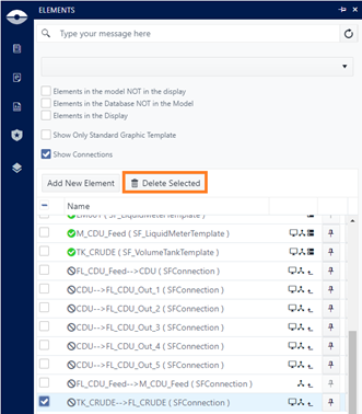
Using the Elements Panel
The connector has to represent a Model connection.
- Open the Elements Panel.
- Search for the connector to be removed. You can use the search box and type the name of the source or destination name to filter the connectors.
- Select the connector.
- Press the Delete Selected button.
By removing a connector between two Graphic Symbols both referencing a Sigmafine Element, then the connection is removed from the Model as well.