Configuring - Liquid Meter Compensation
This configuration can be done at the template or individual Element level. The example procedure shown below is done at the template level.
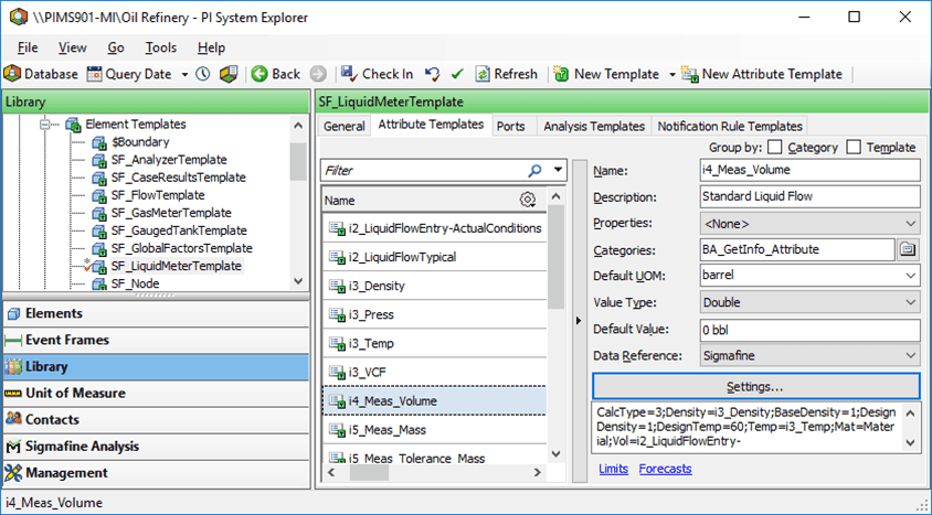
In the System Explorer navigation pane, click on Library.
From the Templates > Element Templates tree, select the liquid meter template (i.e., SF_LiquidMeterTemplate).
Click on the Attribute Templates tab.
In the Name column, select the Attribute for the compensated flow (i.e., i4_Meas_Volume).
Click on the Data Reference down-arrow and select Sigmafine.
Click the Settings button to open the Sigmafine Data Reference window.
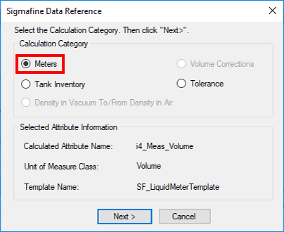
Under Calculation Category select Meters.
Click Next.
The Meters window opens.

Select Liquid Meter Compensation.
Click Next.
The Liquid Meter Compensation window opens.
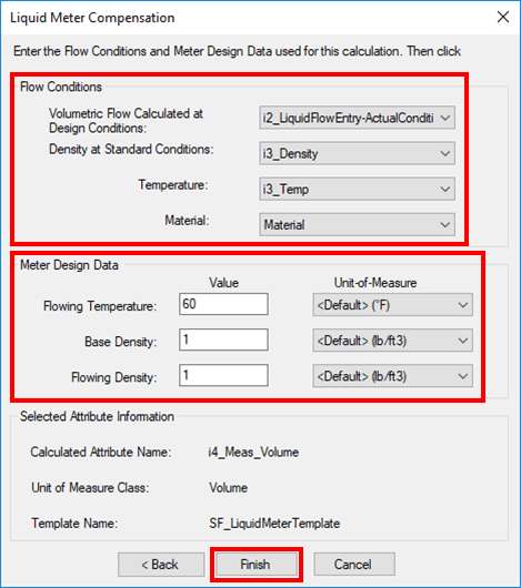
Using the following Flow Conditions table, select the Attributes for Flow Conditions.
Using the following Meter Design Data table, enter/select the Attributes for Meter Design Data.
Note: The Material Attribute for Flow Conditions is the material specified in the flow to which the liquid meter is attached to, not the one specified in the meter.
Flow Conditions
Input Box / Button Description Volumetric Flow Calculated at Design Conditions Select attribute; units = volume Density at Standard Conditions Select attribute; units = density or API. Volume Correction Factor Select attribute; units = liquid volume. Temperature Select attribute; units = temperature. Material Select attribute; units = \<none>. Meter Design Data
Input Box / Button Description Flowing Temperature Select attribute; units = temperature. Base Density (design) Enter meter design base density in the selected unit of density or API. Flowing Density (design) Enter meter design flowing density in the selected unit of density or API. When finished, click Finish to complete the configuration.
The following sample displays the configuration in the System Explorer window.