Configuring - Analyzer Configuration
Use the Analyzer Configuration option to establish which Attribute in the Element holds the component configuration. You can also select a source PI Point for each component included in the configuration.
The Analyzer Configuration option populates the component data Attribute within an analyzer element. This Attribute is a data table that contains the following information:
- Component names
- Component measurements
- Component measurement tolerances
After Attribute configuration, the component information is retrieved from an AF table named "SF_Component Table." See Editing the SF_Component Table for information about its contents.
To configure Analyzer:
Select the analyzer Element and the component data Attribute to load the compositions.
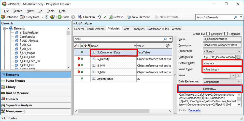
For the attribute’s Data Reference Name, select ComponentData.
The Default UOM value should be None.
The Value Type should be Anything.
Click the Settings button.
The Components Data Reference window opens.
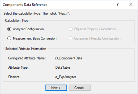
Under Calculation type, select Analyzer Configuration, then click Next.
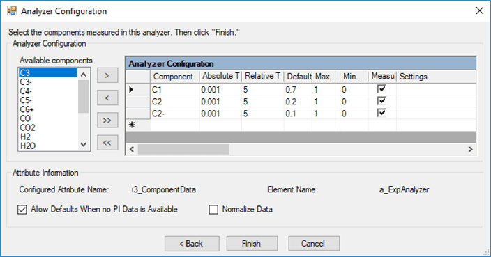
The Analyzer Configuration window opens.
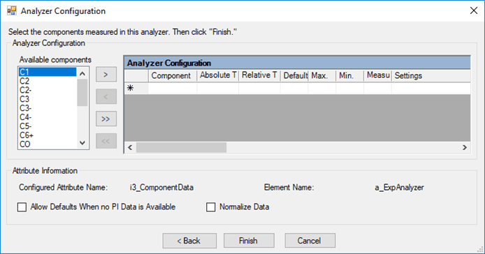
Fill the Analyzer Configuration window as described in the table below.
Analyzer Configuration Dialog Box
Input Box / Button Description Available components (list) Select a component or multiple components. (Use the arrows to select the components to measure.)The component list is from the table SF_Component. Analyzer Configuration (table) Component – Name of component that has been selected. Absolute Tolerance – Enter the absolute tolerance for the component; units = UOM of the component measurement. Relative Tolerance – Enter the Relative tolerance for the component; units = %. Default – Enter the default value for the component; units = UOM of the component measurement. Max. 1 – Enter the maximum value for the component; units = UOM of the component measurement. Min. 1 – Enter the minimum value for the component; units = UOM of the component measurement. Measured – Check the box to indicate that the value is measured. Uncheck the box if the value is not measured and is to be estimated by an analysis. Settings – Select the settings cell then right-click the cell and select PI Point. See ‘Configuring the PI Point for a Component’ for configuring a PI Point. You must check the Measured check box before you can configure settings for the component. Allow Defaults When no PI Data is Available (checkbox) Select this checkbox to substitute default values in the table when no data is available from the PI point.The default values are specified in the Default column for each component. Normalize Data (checkbox) Select this checkbox to force the total of component values to be 1 through normalization.NOTE: Use this feature carefully and do not choose it by default. Normalization changes the values for the components to force the sum total to be exactly 1. For example, for two components with readings of 0.1 and 0.1, normalization causes adjustments to 0.5 and 0.5 respectively. Normalization is useful only when the sum of the fractions is not 1 or sometimes more than 1 (due to precision problems in chemical analysis). 1 These values are not used for clamping (limiting) the value. They are used as a check in the Gross Error Analysis Rule. To specify the PI point that stores the measurement information for each component, follow the steps under Configuring the PI Point for a Component.
When done with your configuration settings, click Finish.
Configuring the PI Point for a Component
Use the following steps to specify the PI Point that stores the measurement information for each component.
Right-click the component as shown in the following image.
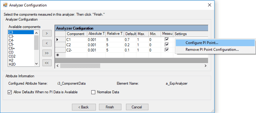
Select Configure PI Point from the right-click menu.
The PI Point Data Reference window opens.
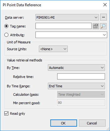
Fill out the PI Point Data Reference window.
Use the information found under the “Data References" chapter in the PI AF User Guide, for detailed instructions about configuring the PI Point Data Reference.
When finished, click OK to save your settings and close the PI Point Data Reference window.