Build a Whiteboard
Add Graphic Symbol to the Display
Graphic symbols are added to a display by dragging a symbol from the Whiteboard library.
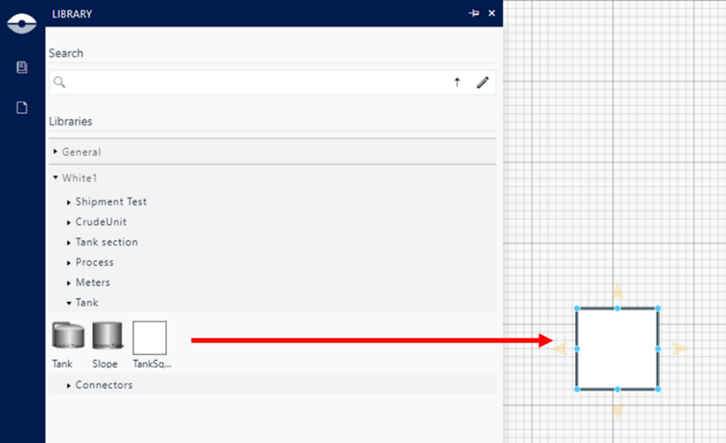
The graphic symbol is not in relation to any Sigmafine Element template, and it is only characterized by its Tag attribute value assigned in the graphic symbols� library.
The Tag attribute value will be used by the Whiteboard converter (Graphic Template Tag step) asking to link the Taf to a Sigmafine Element Template.
A graphic symbol name can be assigned from the Symbol Property Panel by filling the Name text box.
This is the name assigned to Sigmafine Element that will be created in the Model by the Whiteboard converter.
Add Connector
In the context of a Whiteboard display, a connector is a line connected to one or two graphic symbols.
The following example shows the connector drawn between a flow of material from a tank to a process unit.

The Connector between graphic symbols will be associated to Sigmafine Elements and will be replaced by a flow in the Sigmafine Model during the conversion.
The Whiteboard Converter performs some validation rules with the objective to:
- Discover duplicated connectors (connections).
- Recognize connectors that must be interpreted as connections.
Duplicate connectors are always excluded.
Duplicate connectors from A to B


The only exception to this rule applies to process units

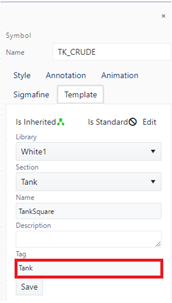
A connector is a valid Model connection only if the connected objects respect the following Sigmafine modelling constraints:
Sigmafine template that refers to a graphic symbol A:
- [Scenario 1] Must have an Output port.
- The connection count does not exceed the Maximum Connections.
- Element Template B must be consistent with Allowed Templates.
- Element Type B must be consistent with the Connection Type.
Sigmafine template that refers to graphic symbol B:
- [Scenario 1] Must have an Input port.
- [Scenario 2] Must have an Indirect port.
- The connection count does not exceed the Maximum Connections.
- Element Template A must be consistent with Allowed Templates.
- Element Type A must be consistent with the Connection Type.
Add Measurement to Connector
Since a connector is considered as a flow by the Converter, users may want to associate a measurement to the connector. This can be accomplished by two methods.
- By placing a meter in proximity of the connector

- Placing the meter as part of the same connector

Connected meters are replaced by flow Elements and linked to them, meters placed near a connector follow the same transformation.
Single meter (proximity)

Meter A is in proximity to the connector, and it will be associated to the connector.
Meter B is outside the proximity range, and it will be skipped.
Single meter as part of the connector

Meter A, is part of the same connector and it will be associated to the connector.
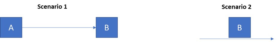
Redundant meters (proximity)
Meters A and B are in proximity of the same connector, and they will be associated to the connector.
Meter C is outside the proximity range, and it will be skipped.
Redundant meters as part of the connector

Meters A, B and C are part of the same connection and it will be associated to the same connector.
Using Whiteboard Display Views
A Whiteboard can be organized across multiple pages (display Views) where each View can contain a partial representation of the modelled process.
When the Whiteboard is converted to a Sigmafine Model, all the plant schematics, which are scattered across the display Views, will be processed to create the Model.
Creating Whiteboard display Views use the same methodology as for creating AF Display Views (see DISPLAY VIEWS MANAGEMENT).