Convert Whiteboard to Model
The Whiteboard Converter converts a Whiteboard draft into a working Sigmafine Model, providing a set of functionalities, consistency checks and the automatic implementation of Sigmafine rules including:
- Definitions of Flows and Nodes.
- Linking of meters to flows.
Four steps are required to convert a Whiteboard draft into a Sigmafine Model.
Progressing forward is blocked unless the current step is complete and valid, moving back to a previous step and changing it will automatically invalidate the step and all steps after it.
Step 1 - Validation
This is the step performing the preliminary validation of the Whiteboard. The validation is not performed towards the target Sigmafine database, and it is a formal validation having the objective to detect:
- Wrong names assigned to the Graphic Symbols.
- Connectors validation.
- Inconsistent duplicated symbols.
Any error detected in this phase prevents the execution of the next steps. The user is required to fix the error on the Whiteboard prior to moving forward. Validation Rules
Symbol name validation:
- The name cannot contain special characters such as: * ' ? ; { } [ ] | ` " \
- The length of a name must be less than or equal to 160 characters.
- A tagged symbol is required to have a name assigned.
Any symbol containing a wrong name is invalidated.
Connectors validation:
- Any connector not attached to a source symbol or destination symbol is excluded from the next checks.
- Check that the source and destination symbols of a connector are valid symbols existing in the display.
- Check that any symbol assimilable to a measurement associated with the connector is a valid symbol.
Duplicated names:
- Symbols with the same name but different tag raise an error. Different tags can potentially be linked to different Sigmafine templates.
- Duplicated symbols names are detected and logged.
Run the Validation Step
To run the validation, click on the validate button to initiate the validation process, during which the application will be blocked by a loading screen, once completed the Whiteboard would be valid and the user could progress forward, or the validation could fail to stop the process to let the user correct the settings and revalidate again. Logs can be found in the ‘Log Output’ drop down components after the user validates the Whiteboard.
Step 2 - Sigmafine Server Selection
In this step, specify the destination for the created model by selecting the following:
- Sigmafine Server.
- Sigmafine Database.
- Sigmafine Model.
- Model Version.
The target model must be created in the Sigmafine database before starting the conversion process, and it must be empty without any existing Element or connection.
Step 3 - Graphic Template Tags
A table listing all Graphic Templates used in the display with their relative Tags is shown and the user shall choose from a drop-down list the related Sigmafine Template to be associated. The list of Sigmafine Templates is provided by the Sigmafine server based on the selections made in the previous step. Assigning all templates to graphic symbols is optional and could be skipped to move to the final step.
Step 4 - Conversion
Conversion Validation Rules
In this phase, the Whiteboard display graphic symbols are validated against the Sigmafine server. The presence of duplicate names is an acceptable condition if several instances of the same Element are on the display. This behavior is aimed to facilitate the representation of the process to be modelled.:
- Duplicate names referring to different types of objects are not allowed. As an example, the name “CRUDE’' cannot be assigned to a meter and at the same time to a process unit.
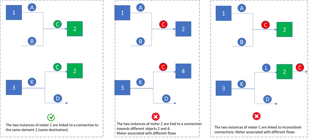
- Duplicate names referring to the same type of objects are allowed if there are no inconsistent connections. In this case, a confirmation message is required.
- If the duplicated object refers to a measurement (meter), then this additional constraint must be respected: Duplicated meters refer to connectors that have either the same source or the same destination.
- Duplicate meters / analyzers that do not refer to a connector are not allowed.
- If the duplicated object refers to an analyzer, then one of the following constraints must be respected:
- Duplicate analyzers refer to connectors that have either the same source or the same destination (like what was said for meters).
- Duplicate analyzers refer to the same type of object (e.g., the same tank).
Some examples are shown below.
Transformation Rules
Flow creation

When a meter is connected or placed near a connector (proximity) and the connector is a connection between two AF Elements, then a new flow Element is created and added to the Model and the meter is attached to the flow.
Flow and Node Creation
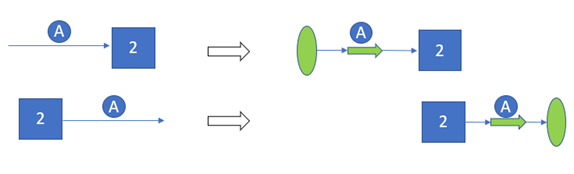
When a meter is connected or is placed near a connector and the connector is linked to an AF Element only:
- A new Flow Element is created and added to the Model, the meter is attached to the Flow.
- A new Node Element is created and added to the Model, the Node is added to the connection.
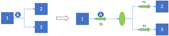
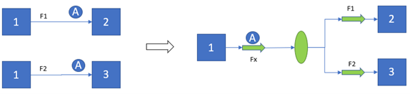
When a meter is connected or is placed near two or more connectors representing an AF connection, all connectors are linked to the same source Element:
- A new Flow Element is created and added to the Model, the meter is attached to the Flow.
- A new Node Element is created and added to the Model, the flow is connected to the Node.
- Two (or more) new flows Elements are added, the Node is connected to the new Flow Elements.
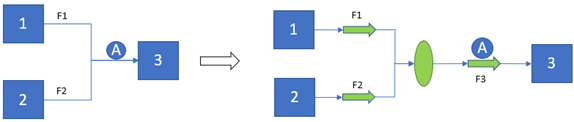
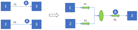
When a meter is connected or is placed near two or more connectors representing an AF connection and all connectors are linked to the same destination Element:
- A new Flow Element is created and added to the Model, the meter is attached to the Flow.
- A new Node Element is created and added to the Model, the Node is connected to the Flow.
- Two (or more) new Flow Elements are added, all new Flow Elements are connected to the Node.
If a Meter is duplicated and all connectors have the same source Element and different destination Element:
- A new Flow Element is created and added to the Model, the meter is attached to the Flow.
- A new Node Element is created and added to the Model, the Flow is connected to the Node.
- Two (or more) new Flow Elements are added, the Node is connected to all the new Flow Elements.
A Meter is duplicated, all connectors have different source Elements and the same destination Element.
- Two or more new Flow Elements are added.
- A new Node Element is added, the new Flow Elements are connected to the new Node.
- A new Flow Element is added, the meter is attached to the new Flow.
- The new Node is connected to the new Flow.
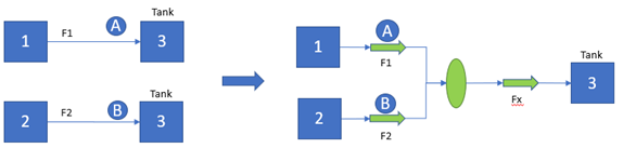
Multiple connectors feeding a tank:
- Two or more new Flow Elements are added with the respective attached meters.
- A new Node Element is added, the new Flow Elements are connected to the new Node.
- A new Flow Element is added.
- The new Node is connected to the new Flow.
Naming Conventions
When flows and nodes are created by the converter, the following naming conventions are applied.
- @Meter = refers to the meter’s name connected to the flow.
- @Source = refers to the name of the source Element of the flow.
- @Destination = refers to the name of the destination Element of the flow.
| Scenario | Assigned name |
|---|---|
| Flow with meter attached | [f_][@Meter] |
| Flow to process unit | [f_][@Destination][_Charge] |
| Flow to tank | [f_][@Destination] |
| Flow to shipment point | [f_][@Destination] |
| Flow to node | [f_][@Destination] |
| Flow from process unit | [f_][@Source][_Out] |
| Flow from receipt point | [f_][@Source] |
| Flow from tank | [f_][@Source][_Out] |
| Flow from node | [f_][@Source] |
In case the applied naming convention leads to create duplicated names, then an auto number is applied.
| Scenario | Description | Assigned name |
|---|---|---|
| Node to process unit | Node with a flow starting from the node itself and ending to a process unit. | [n_][@Destination][_Charge] |
| Node to tank | Node with a flow starting from the node itself and ending to a tank. | [n_][@Destination][_In] |
| Node to shipment | Node with a flow starting from the node itself and ending to a shipment point. | [n_][@Destination] |
| Node from process unit | Node with a flow starting from the process unit and ending to a node itself. | [n_][@Source][_Out] |
| Node from a tank | Node with a flow starting from the tank and ending to a node itself. | [n_][@Source][_Out] |
| Node from receipt point | Node with a flow starting from the receipt point and ending to a node itself. | [n_][@Source] |
Run the Conversion
The final step in the process is to confirm all previous step choices by simply clicking the Convert button where the application will be blocked by a loading screen while the conversion is underway. Once completed a complete, logs are available in the Log Output dropdown Component, and a message indicates whether the process was successful.