New Transfer Action
One of the main functions of the Sigmafine IMM Add-In is the ability to create and configure new transfers (movements). Creating a new transfer action involves two main steps;
Setting Up the General Information
The first step in creating a new transfer action is to setup the transfer's general information in the Transfer Management - New Transfer window, under the 'General Info' tab.
To setup the general information:
- First, open the Transfer Management - New Transfer window.
On the Transfer dockable window toolbar, click the New button.
OR
Right-click on a transfer row and select Transfer Action > New Transfer.
The Transfer Management - New Transfer window opens to the 'General Info' tab.
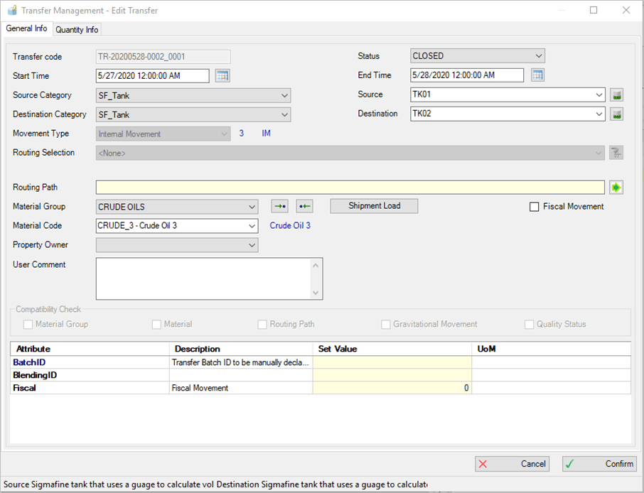
This window consists of two tabs, 'General Info' and 'Quantity Info', both of which contain information that must be compiled with the transfer related information.
Note: You must setup all the pertinent general information prior to setting up the quantity information. The following steps apply to the setup of the general information only. Steps for the quantity information follow in the next section Setting Up the Quantity Information.
The Transfer Code box is automatically filled by the system with a unique name for the transfer.
- Click on the Status box down-arrow and select the status for this transfer. Available options are:
- Planned - Transfer planned; needs to be approved.
- Approved - Transfer not yet started but ready to be activated.
- Active - Transfer started and not yet closed; it is in the running state.
- Closed - Transfer finished and closed.
- Validated - Transfer closed, approved and not editable.
- Click on the Planned Start Time
 calendar button and select the planned start time of the transfer. This box is only visible when the status of the transfer is Approved or Planned.
The 'Planned Start Time' date and time must be set for a future date for both Approved and Planned transfer statuses. If you enter a past date and time, you will receive a warning message.
Note: In lieu of using the calendar button, you can type the planned start time in the box using
mm/dd/yyyy 00:00:00 AM(orPM) format.
- Click on the Planned End Time calendar button and select the planned end time for the transfer. This box is only visible when the status of the transfer is Approved or Planned.
The 'Planned End Time' date and time must be set for an Approved or Planned transfer status, and defined with a future date. If you enter a past date and time, or one that falls before the Planned Start Time, you will receive a warning message.
Note: In lieu of using the calendar button, you can type the planned end time in the box using
mm/dd/yyyy 00:00:00 AM(orPM) format.
- Click on the Start Time calendar button and select the start time of the transfer. This box is only visible when the status of the transfer is Active, Closed or Validated.
The 'Start Time' date and time must be set for an Active transfer status, and defined with the current date.
The 'Start Time' date and time must also be set for a Closed or Validated transfer status, but defined with a past date.
Note: In lieu of using the calendar button, you can type the start time in the box using
mm/dd/yyyy 00:00:00 AM(orPM) format.
- Click on the End Time calendar button and select the end time for the transfer. This box is only visible when the status of the transfer is Active, Closed or Validated.
The 'End Time' date and time must be set for a Closed or Validated transfer status, and defined with a date that is past the 'Start Time' date. If you enter a date that falls before the Start Time date, you will receive a warning message.
Note: In lieu of using the calendar button, you can type the end time in the box using
mm/dd/yyyy 00:00:00 AM(orPM) format.
In the Source box, type the name of the source Element for the transfer.
If you do not know the exact name, use the Search or ... (ellipsis) button to find the source element.
Click on the Source Category down-arrow and select the category of the source element (SF_Node, SF_ReceiptPoint or SF_Tank).
Use the
 button next to 'Source', to load a list of compatible destination Element categories.
Click on the Source down-arrow and select the source of the element.
Use the
button next to 'Source', to load a list of compatible destination elements.Click on the Destination Category down-arrow and select the category of the destination element (SF_Node, SF_ReceiptPoint or SF_Tank).
Note: SF_Process element category could be included int he transfer source and destination according to the configuration parameter AllowTransferToFromProcessUnit in IMM_Params table.
Use the
button next to 'Source', to load a list of compatible source Element categories.Click on the Destination down-arrow and select the destination element.
Use the
button next to 'Source', to load a list of compatible source elements.(Optional) Click on the Movement Type down-arrow and select the parameter by which to filter or group the movements.
The default is set to \<None>.
(Optional) Click the Routing Selection down-arrow and select the routing name you want to use.
Available options consist of all routing names in the IMM_ElemComp table, filtered by source and destination.
You can click on the
 Open Routing Path Advanced filter button to open a window in which you can order the routing paths by Capacity, Length or Element Count. In addition, you can filter the routing paths by the Elements or Instruments that are involved.
The default is set to \<None>, indicating movement from source to destination without other elements.
The Routing Path box displays all the elements involved in the selected paths, separated by the ^ character.
(Optional) Click on the
 Open Routing Path button to open a window in which you can view the description and template of all elements involved in the Routing Path.
Click on the Material Group down-arrow and select the material group.
You can use the Get Material from Source or Get Material from Destination button to assign the transfer of the material of Source or of Destination.
Click on the Material Code down-arrow and select the code for the material to be grouped by your selection in the prior step.
Check the Fiscal Movement checkbox to define the movements that have fiscal relevance.
(Optional) In the User Comment box, type any comments you may have regarding this transfer.
There are some Compatibility Checks that Sigmafine IMM Add-In provides: Material Group, Material, Routing Path, Gravitational Movement and Quality Status. These checks are active by default, but can be deactivate using the associated check boxes.
To deactivate any of the Compatibility Checks, remove the check from the associated checkbox.
The table in the lower part of the form allows you to insert values as needed. The list of rows is customizable and shows the parameters, Attribute Name, Description, Set Value (an editable column) and UoM.
Mandatory transfer’s attributes are highlighted in red. (as shown in the following figure).

Missing values in transfer’s mandatory attributes are raised to the user through an error message.
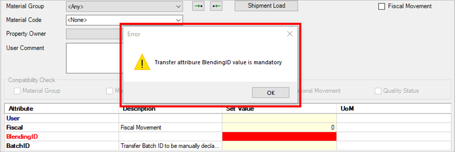
See the \IMM_PARAMS_TABLE topic on how to configure mandatory transfer’s attributes.
If all parameters are properly set under the' General Info' tab, you are now able to configuring the quantity under the 'Quantity Info' tab. However, if information is missing or incorrect for the type of transfer action you are creating, error messages will display. Errors must first be corrected before you can setup the quantity configuration.
Setting Up the Quantity Information
The second step in creating a new transfer action is to setup the transfer's quantity information in the Transfer Management - New Transfer window, under the 'Quantity Info' tab.
To setup the quantity information:
In the Transfer Management - New Transfer window, click on the Quantity Info tab.
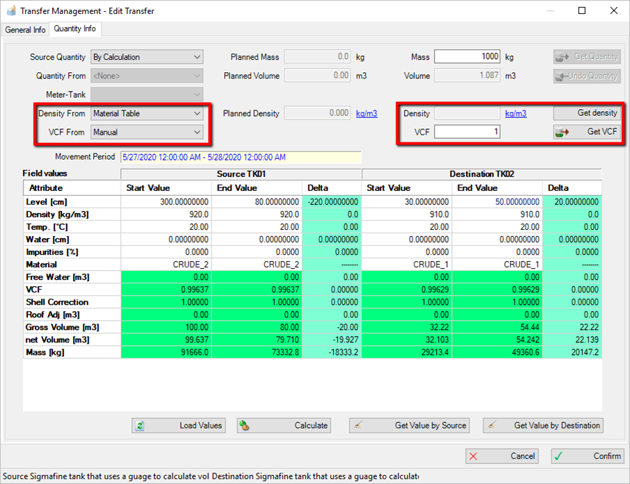
The window displays the available quantity information configuration options.
Density boxes
In early versions of IMM, the Quantity Info tab provided support to declare the transfer quantity using the material density picked up from the Sigmafine material table.
Starting from IMM 4.7 SP2, the density used to calculate the mass, or the volume of the transfer can be taken from sources other than the Sigmafine material table. Those sources are:
Manual input
Sigmafine material table
Source or destination tank
Meter
Source or destination node
The available options are listed in the Density From dropw-down list, according to the source or destination elements of the transfer and the availability of the density measurement.
When the Source Node or Destination Node option is selected, the density is calculated as an average density of the inlet meters or outlet meters. The following formula is used:

Where:
V = Volume
D = Density
Note: The availability of the density measurement depends on whether the source element has an available density attribute, and it is configured in IMM (see
Meter Settings and Tank SettingsinIMM_Paramsconfiguration table).Volume Correction Factor (VCF)
Starting from IMM 4.7 SP2, the mass calculated using the volume and the density can include the volume correction factor (VCF) in order to obtain a more precise mass or volume estimation of the transfer. The formula is as follows:
Mass = Volume * Density * VCF
Volume = Mass / Density / VCF
The VCF used to calculate the mass, or the volume of the transfer, can be taken from the following sources:
Manual input
Source or destination tank
Meter
Source or destination node
The possible options are listed in the‘VCF from drop-down list, according to the source or destination elements of the transfer and the availability of the VCF measurement.
When the Source Node or Destination Node option is selected, the VCF is calculated as an average VCF of the inlet meters or outlet meters. The following is the formula used:

Where:
V = Volume
D = Density
Note: The availability of the VCF measurement depends by whether the source element has an available VCF attribute, and it is configured in IMM (see
Meter Settings and Tank SettingsinIMM_Paramsconfiguration table).The Movement Period box displays the information related to the start time and end time movement. This time range is the reference for retrieving the Attribute values.
Quantity can either be manually entered, or you can allow the system to calculate it by selecting the source of the quantity.
To manually enter the quantity, type the value(s) into the box(es) appropriate for this transfer.
To allow the system to calculate the quantity:
Click the Source Quantity down-arrow and select By Calculation.
Use the following table to determine how to get the quantity for this transfer.
Available Options for Calculating Quantity
Input Box / Button Description Meter - Tank Click on this down-arrow to choose the Element name from a list of available elements. If the selected Element is a tank, the quantity is calculated as 'DeltaStock'. If the selected Element is a meter, the quantity is calculated as meter 'Totalization' in the period of the running transfer.You can click on the Meter-Tank label to filter by meter only or tank only.Note: Starting with this version, you can use the ‘Load Values’ button to load information about the selected meter or tank, in order see or change input data. Source Select this option to evaluate the quantity from the delta stock calculation of the source element. Destination Select this option to evaluate the quantity from the delta stock calculation of the destination element. Click this button to read in the source or destination quantity, depending on which you have selected. Click this button to reset the calculated quantity and set the quantity to the starting value. Click the
 Load Values button to load the information with source and destination data (tank calculation) or meter data (meter calculation).
When clicked, three columns of data are loaded for the source tank and destination tank. This information consists of the following:
Start Value: The value at the start tine of the transfer.
End Value: The value at the end of the transfer.
Delta: The difference between the start and end values for each Attribute in the list.
The Attribute list is configured in AF table named 'IMM_TankInvConf'. Every cell color has a specific meaning, which is as follows:
White: Represents values that are editable .
Bright blue: Represents values reserved for delta column
Green: Represents values calculated by tank calculation
Red: Represents a value that is incorrect (for example, a non-numeric value inserted in a numeric value cell)
Gray: Represents locked values read by the AF element
Click the
 Calculate button to execute the calculation.
If no errors are present, the 'Get Value by Source' and 'Get Value by Dest.' buttons become enabled. In addition, the quantity value is set in the corresponding field according to the tank calculation plug-in.
Click the Get Value by Source or Get Value by Dest. button to read the values in.
When the Quantity is evaluated, you are ready to confirm it.
Click the
 Confirm button.
The insertion is confirmed and the new transfer row is added in the dockable window.
When you specify whether the quantity must be calculated using the Source/Destination tank, the same information is saved at the Transfer level so that it is possible to recalculate the data present in the transfer before the calculation.
The tank delta stock is assigned to the transfer as an absolute value by default, since the quantity of the transfer should be expressed as a positive value. What this means is that whenever a destination element in transfer creation decreases in volume, this negative delta is assigned to the transfer as positive value.
If is required to transpose the negative value to the transfer as a default behavior, this can be accomplished by setting the parameter ‘TransposingNegativeTransfer=true’ in IMM_Params table.
If your choose to click the Cancel button, the new transfer definition is discharged.
Note: Please note that it is important to properly configure the transfer template as explained throughout the remaining \topics under IMM in this Online Help.
Meter Calculation
When meter calculation is selected, meter attributes are loaded according to the attribute list configured in the AF table named 'IMM_TankInvConf' for Mass Volume meters.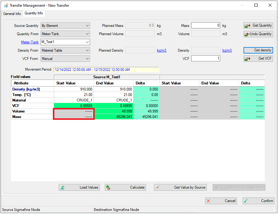
In some cases, the ‘Start Value’ column may be empty, to indicate that the attribute value is the result of a totalization over the time interval determined by the start/end time of the transfer. In such a case, the totalized value is shown in the ‘End Value’ column.