Configure IF Virtual Data Set
To configure an IF Virtual Data Set:
Run the Integration Framework - Configurator application.
The Integration Framework - Configurator window opens.
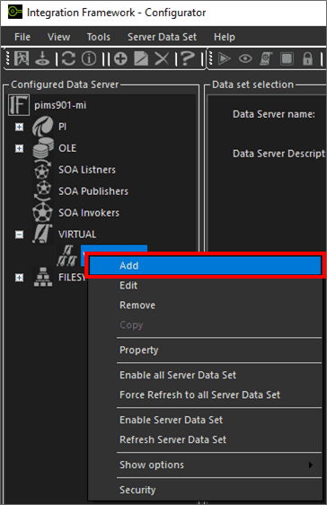
In the Configured Data Server pane, click on the VIRTUAL Data Server to which you want to add a Data Set.
In the toolbar, click the
 Add icon.
Alternatively, you can right-click on the PI Server and select the Add option as shown in the following figure.
The Configure Virtual Data Server Source window opens.

Before you can work in this window, you need to activate the "Available Sources" panel. The panel allows you to select the IF objects to be consumed and used to feed an IF object.
In the toolbar, click the
 Virtual Data tree icon to expand the Data Server tree.
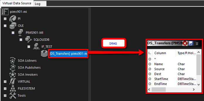
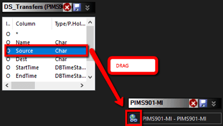
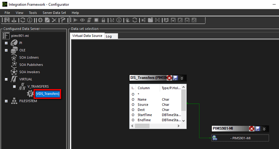
Locate and select the Data Set to be consumed and drag it onto the right panel (as shown in Figure 1433).
In our example, we have used the OLE DB Data Set (DS_Transfers), in order to import them into our PI Data Server (PIMS901-MI).
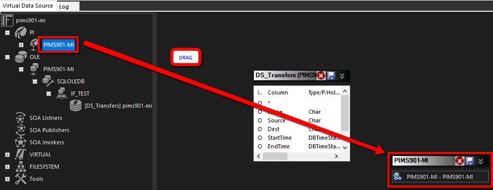
Locate and select the Data Server into which the Data Set is to be consumed and drag it onto the right panel, as shown in the following figure.
The next step is to connect the source OLE Database Data Set (in our example, DS_Transfers) to the destination PI Data Server (in our example PIMS902-MI). This is done by selecting a row in the Data Set window and dragging it over the PI Data Server icon.
Select one of the rows in the Data Set and drag it onto the top of the Data Server connection icon, as shown in the following figure.
When the connection completes successfully, a connector is displayed, as shown in the following figure.
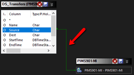
Double-click on the
 PI Server connection icon to activate the settings window.
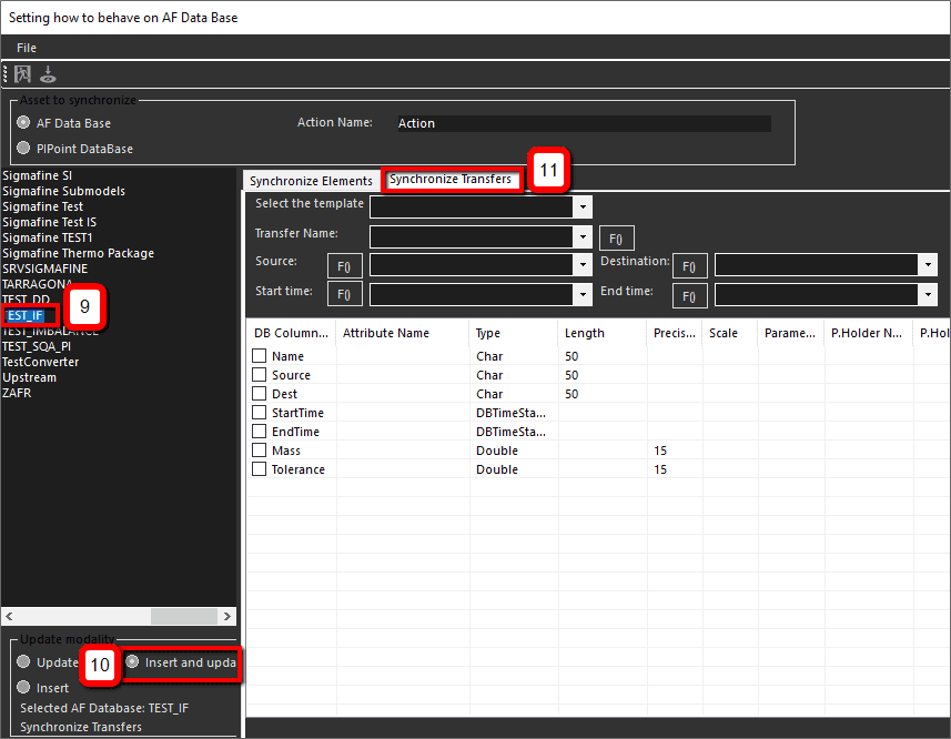
In this window you set up the preliminary setting of the connected PI Data Server.
In the pane on the left, select the Sigmafine database in which to import the transfers.
Under Update Modality, select the Insert and update option.
Click on the Synchronize Transfers tab to open its panel.
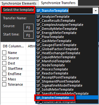
Click on the Select the template down-arrow, and select the appropriate template to be used to create the transfers (in our example this would be the SF_TransferTemplate).
Next, you need to map the Data Set column that contains the transfer's name.
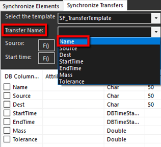
Click on the Transfer Name down-arrow and select the Name item.
This action maps the Transfer Name to the Name item. Now you need to map the Data Set columns containing the transfer source, destination, start time and end time.
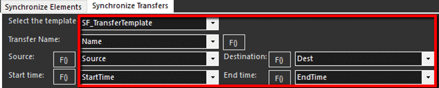
Click the Source down-arrow and select the Source item.
Click the Start time down-arrow and select the StartTime item.
Click the Destination down-arrow and select the Dest item.
Click the End time down-arrow and select the EndTime item.
Now you define where to store the Data Set column 'Mass' in the transfer attribute.
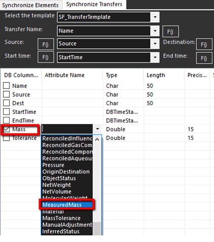
Check the Mass checkbox.
Click on the Mass, Attribute Name cell down-arrow and select MeasuredMass.
Next, you assign a name to the configured action.

In the Action Name box, type a name for the configured action.
Click the
 Save and Exit icon.
You are returned to the Configure Virtual Data Server Source window, Virtual Data Source tab.
Click the
Save and Exit icon in the Virtual Data Server Source window, to save the Virtual Data Server.You are returned to the Virtual data set settings window, where you assign a name to the Data Set.
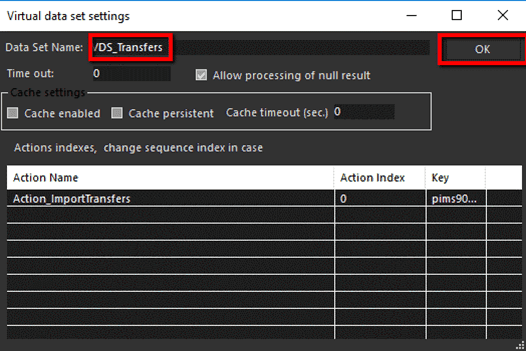
In the Data Set Name box, type a name for the Data Set.
Click OK to save the new Data Set and return to the Integration Framework - Configurator main window.
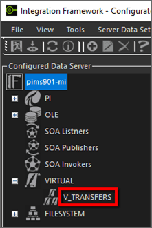
The Data Set you just saved is now displayed in the VIRTUAL tree in the Configured Data Server pane.
The last action is to test the Virtual Data Set.
In the configured Data Server pane, locate and click on the Virtual Data Set you just configured, to select it.
In the toolbar, click on the
 Preview icon.
A preview of the input OLE DB Data Set is displayed, and the configured action over the AF Data Base is performed. The results are displayed in the VirtualPreviewSequence window, as shown in the following figure.
