Displaying AF Data as a Multi-State Symbol
The following steps describe how to display AF data in a multi-state symbol.
IMPORTANT: You must be in Build mode to perform the following steps.
To display AF data as a multi-state symbol:
Open a Model display.
Select Edit > Multi-State, as shown in the following figure.
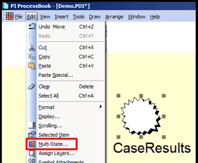
The Multi-State Symbol window opens.
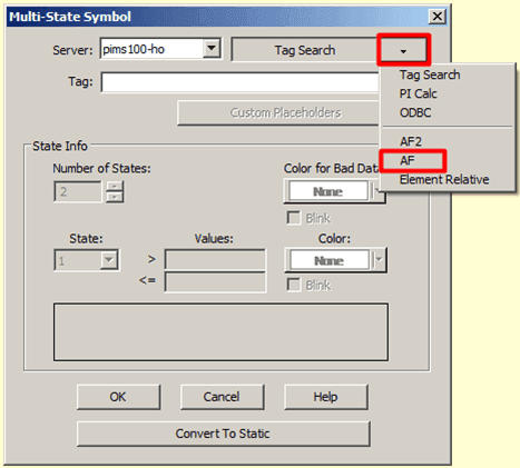
Click on the Tag Search down-arrow and select AF, as shown in Figure 906.
The AF Element Configuration window opens.
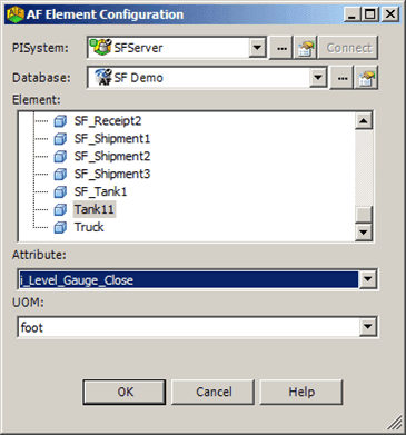
In the Element list, select the Element you want to configure.
Click on the Attribute down-arrow and select the Attribute of that element.
Click OK to save your selections.
A second AF Element Configuration window opens, in which you can define the states and color for various ranges of values. In the following figures, we are showing two states being defined, with one colored in green and the other in red.
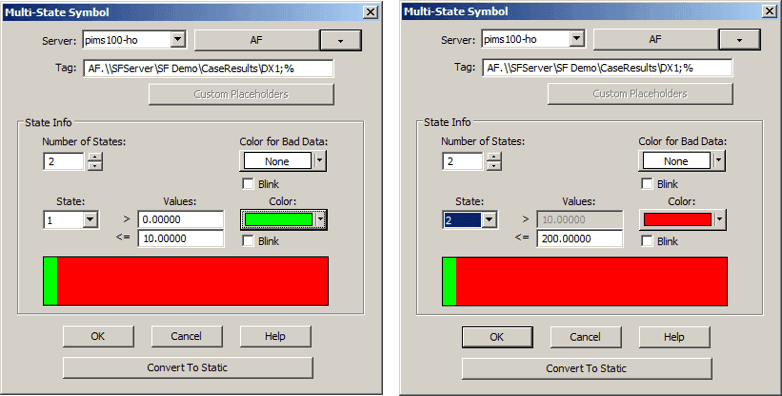
Click the Number of States up or down arrow to select the number of states you want to define.
In our steps, we are defining two (2) states for the selected element/attribute.
(Optional) Click the Color for Bad Data down-arrow and select the symbol color for that represents bad data. The default is "none".
(Optional) Check the Blink checkbox if you want the Bad Data symbol in the display to blink.
Click the State down-arrow and select which state you are defining, beginning with the first state.
In the first Values box, type the starting value for the range associated with the selected state.
In (0.00000 indicates any value that is more than "0").
This step is only required for the very first (1) state you are defining. All other states (2 and above) use the ending value of the previous state as their starting value.
In the second Values box, type the ending value for the selected state (10.00000 indicates any value that is less than, or equal to 10.00000).
This step is required for all states you are defining.
Click the Color down-arrow and select the color to the state.
(Optional) Check the Blink checkbox if you want the symbol, that represents this state in the display, to blink.
Repeat steps 10, 12, 13 and 14 for all remaining states that you need to define.
The number of states you have to define depends on the number you selected for the Number of States in step 7.
When finished, click OK to save your definitions and close the Multi-State Symbol window.
The symbol is now able to assume the multiple states you have defined.
